Search This Blog

Thursday, 2 August 2012

DICOM

DICOM (Digital Imaging and Communications in Medicine) is a standard for handling, storing, printing, and transmitting information in medical imaging. It includes a file format definition and a network communications protocol. The communication protocol is an application protocol that uses TCP/IP to communicate between systems. DICOM files can be exchanged between two entities that are capable of receiving image and patient data in DICOM format. The National Electrical Manufacturers Association (NEMA) holds the copyright to this standard.[1] It was developed by the DICOM Standards Committee, whose members[2] are also partly members of NEMA.[3]
DICOM enables the integration of scanners, servers, workstations, printers, and network hardware from multiple manufacturers into a picture archiving and communication system (PACS). The different devices come with DICOM conformance statements which clearly state which DICOM classes they support. DICOM has been widely adopted by hospitals and is making inroads in smaller applications like dentists' and doctors' offices.

History


Front page of ACR/NEMA 300, version 1.0, which was released in 1985
DICOM is the third version of a standard developed by American College of Radiology (ACR) and National Electrical Manufacturers Association (NEMA).
In the beginning of the 1980s, it was very difficult for anyone other than manufacturers of computed tomography or magnetic resonance imaging devices to decode the images that the machines generated. Radiologists and medical physicists wanted to use the images for dose-planning for radiation therapy. ACR and NEMA joined forces and formed a standard committee in 1983. Their first standard, ACR/NEMA 300, was released in 1985. Very soon after its release, it became clear that improvements were needed. The text was vague and had internal contradictions.
In 1988 the second version was released. This version gained more acceptance among vendors. The image transmission was specified as over a dedicated 25 differential (EIA-485) pair cable. The first demonstration of ACR/NEMA V2.0 interconnectivity technology was held at Georgetown University, May 21–23, 1990. Six companies participated in this event, DeJarnette Research Systems, General Electric Medical Systems, Merge Technologies, Siemens Medical Systems, Vortech (acquired by Kodak that same year) and 3M. Commercial equipment supporting ACR/NEMA 2.0 was presented at the annual meeting of the Radiological Society of North America (RSNA) in 1990 by these same vendors. Many soon realized that the second version also needed improvement. Several extensions to ACR/NEMA 2.0 were created, like Papyrus (developed by the University Hospital of Geneva, Switzerland) and SPI (Standard Product Interconnect), driven by Siemens Medical Systems and Philips Medical Systems.
The first large-scale deployment of ACR/NEMA technology was made in 1992 by the US Army and Air Force, as part of the MDIS (Medical Diagnostic Imaging Support) program run out of Ft. Detrick, Maryland. Loral Aerospace and Siemens Medical Systems led a consortium of companies in deploying the first US military PACS (Picture Archiving and Communications System) at all major Army and Air Force medical treatment facilities and teleradiology nodes at a large number of US military clinics. DeJarnette Research Systems and Merge Technologies provided the modality gateway interfaces from third party imaging modalities to the Siemens SPI network. The Veterans Administration and the Navy also purchased systems off this contract.
In 1993 the third version of the standard was released. Its name was then changed to "DICOM" so as to improve the possibility of international acceptance as a standard. New service classes were defined, network support added and the Conformance Statement was introduced. Officially, the latest version of the standard is still 3.0. However, it has been constantly updated and extended since 1993. Instead of using the version number, the standard is often version-numbered using the release year, like "the 2007 version of DICOM".
While the DICOM standard has achieved a near universal level of acceptance amongst medical imaging equipment vendors and healthcare IT organizations, the standard has its limitations. DICOM is a standard directed at addressing technical interoperability issues in medical imaging. It is not a framework or architecture for achieving a useful clinical workflow. RSNA's Integrating the Healthcare Enterprise (IHE) initiative layered on top of DICOM (and HL-7) provides this final piece of the medical imaging interoperability puzzle.

Derivations

There are some derivations from the DICOM standard into other application areas. These include:
  • DICONDE - Digital Imaging and Communication in Nondestructive Evaluation, was established in 2004 as a way for nondestructive testing manufacturers and users to share image data.[5]
  • DICOS - Digital Imaging and Communication in Security was established in 2009 to be used for image sharing in airport security.[6]

DICOM data format

DICOM differs from some, but not all, data formats in that it groups information into data sets. That means that a file of a chest x-ray image, for example, actually contains the patient ID within the file, so that the image can never be separated from this information by mistake. This is similar to the way that image formats such as JPEG can also have embedded tags to identify and otherwise describe the image.
A DICOM data object consists of a number of attributes, including items such as name, ID, etc., and also one special attribute containing the image pixel data (i.e. logically, the main object has no "header" as such: merely a list of attributes, including the pixel data). A single DICOM object can have only one attribute containing pixel data. For many modalities, this corresponds to a single image. But note that the attribute may contain multiple "frames", allowing storage of cine loops or other multi-frame data. Another example is NM data, where an NM image, by definition, is a multi-dimensional multi-frame image. In these cases, three- or four-dimensional data can be encapsulated in a single DICOM object. Pixel data can be compressed using a variety of standards, including JPEG, JPEG Lossless, JPEG 2000, and Run-length encoding (RLE). LZW (zip) compression can be used for the whole data set (not just the pixel data), but this has rarely been implemented.
DICOM uses three different Data Element encoding schemes. With Explicit Value Representation (VR) Data Elements, for VRs that are not OB, OW, OF, SQ, UT, or UN, the format for each Data Element is: GROUP (2 bytes) ELEMENT (2 bytes) VR (2 bytes) LengthInByte (2 bytes) Data (variable length). For the other Explicit Data Elements or Implicit Data Elements, see section 7.1 of Part 5 of the DICOM Standard.
The same basic format is used for all applications, including network and file usage, but when written to a file, usually a true "header" (containing copies of a few key attributes and details of the application which wrote it) is added.

DICOM value representations

Extracted from Chapter 6.2 of
Value Representation Description
AE Application Entity
AS Age String
AT Attribute Tag
CS Code String
DA Date
DS Decimal String
DT Date/Time
FL Floating Point Single (4 bytes)
FD Floating Point Double (8 bytes)
IS Integer String
LO Long String
LT Long Text
OB Other Byte
OF Other Float
OW Other Word
PN Person Name
SH Short String
SL Signed Long
SQ Sequence of Items
SS Signed Short
ST Short Text
TM Time
UI Unique Identifier
UL Unsigned Long
UN Unknown
US Unsigned Short
UT Unlimited Text
In addition to a Value Representation, each attribute also has a Value Multiplicity to indicate the number of data elements contained in the attribute. For character string value representations, if more than one data element is being encoded, the successive data elements are separated by the backslash character "\".

DICOM services

DICOM consists of many different services, most of which involve transmission of data over a network, and the file format below is a later and relatively minor addition to the standard.

Store

The DICOM Store service is used to send images or other persistent objects (structured reports, etc.) to a PACS or workstation.

Storage commitment

The DICOM storage commitment service is used to confirm that an image has been permanently stored by a device (either on redundant disks or on backup media, e.g. burnt to a CD). The Service Class User (SCU: similar to a client), a modality or workstation, etc., uses the confirmation from the Service Class Provider (SCP: similar to a server), an archive station for instance, to make sure that it is safe to delete the images locally.

Query/Retrieve

This enables a workstation to find lists of images or other such objects and then retrieve them from a PACS.

Modality worklist

This enables a piece of imaging equipment (a modality) to obtain details of patients and scheduled examinations electronically, avoiding the need to type such information multiple times (and the mistakes caused by retyping).

Modality performed procedure step

A complementary service to Modality Worklist, this enables the modality to send a report about a performed examination including data about the images acquired, beginning time, end time, and duration of a study, dose delivered, etc. It helps give the radiology department a more precise handle on resource (acquisition station) use. Also known as MPPS, this service allows a modality to better coordinate with image storage servers by giving the server a list of objects to send before or while actually sending such objects.

Printing

The DICOM Printing service is used to send images to a DICOM Printer, normally to print an "X-Ray" film. There is a standard calibration (defined in DICOM Part 14) to help ensure consistency between various display devices, including hard copy printout.

Off-line media (DICOM files)

The off-line media files correspond to Part 10 of the DICOM standard. It describes how to store medical imaging information on removable media. Except for the data set containing, for example, an image and demography, it's also mandatory to include the File Meta Information.
DICOM restricts the filenames on DICOM media to 8 characters (some systems wrongly use 8.3, but this does not conform to the standard). No information must be extracted from these names (PS3.10 Section 6.2.3.2). This is a common source of problems with media created by developers who did not read the specifications carefully. This is a historical requirement to maintain compatibility with older existing systems. It also mandates the presence of a media directory, the DICOMDIR file, which provides index and summary information for all the DICOM files on the media. The DICOMDIR information provides substantially greater information about each file than any filename could, so there is less need for meaningful file names.
DICOM files typically have a .dcm file extension if they are not part of a DICOM media (which requires them to be without extension).
The MIME type for DICOM files is defined by RFC 3240 as application/dicom.
The Uniform Type Identifier type for DICOM files is org.nema.dicom.
There is also an ongoing media exchange test and "connectathon" process for CD media and network operation that is organized by the IHE organization. MicroDicom is free Windows software for reading DICOM data.

Application areas

Modality Description
AS Modality of type Angioscopy - Retired
BI Modality of type Biomagnetic Imaging
CD Modality of type Color Flow Doppler - Retired 2008
CF Modality of type Cinefluorography - Retired
CP Modality of type Colposcopy - Retired
CR Modality of type Computed Radiography
CS Modality of type Cystoscopy - Retired
CT Modality of type Computed Tomography
DD Modality of type Duplex Doppler - Retired 2008
DG Modality of type Diaphanography
DM Modality of type Digital Microscopy - Retired
DS Modality of type Digital Subtraction Angiography - Retired
DX Modality of type Digital Radiography
EC Modality of type Echocardiography - Retired
ECG Modality of type Electrocardiograms
EM Modality of type Electron Microscope
ES Modality of type Endoscopy
FA Modality of type Fluorescein Angiography - Retired
FS Modality of type Fundoscopy - Retired
GM Modality of type General Microscopy
HC Modality of type Hard Copy
LP Modality of type Laparoscopy - Retired
LS Modality of type Laser Surface Scan
MA Modality of type Magnetic Resonance Angiography (retired)
MG Modality of type Mammography
MR Modality of type Magnetic Resonance
MS Modality of type Magnetic Resonance Spectroscopy - Retired
NM Modality of type Nuclear Medicine
OP Modality of type Ophthalmic Photography
OPM Modality of type Ophthalmic Mapping
OPR Modality of type Ophthalmic Refraction
OPV Modality of type Ophthalmic Visual Field
OT Modality of type Other
PT Modality of type Positron Emission Tomography (PET)
RD Modality of type Radiotherapy Dose (a.k.a. RTDOSE)
RF Modality of type Radio Fluoroscopy
RG Modality of type Radiographic Imaging (conventional film screen)
RTIMAG Modality of type Radiotherapy Image
RP Modality of type Radiotherapy Plan (a.k.a. RTPLAN)
RS Modality of type Radiotherapy Structure Set (a.k.a. RTSTRUCT)
RT Modality of type Radiation Therapy
SC Modality of type Secondary Capture
SM Modality of type Slide Microscopy
SR Modality of type Structured Reporting
ST Modality of type Single-Photon Emission Computed Tomography (retired 2008)
TG Modality of type Thermography
US Modality of type Ultrasound
VF Modality of type Videofluorography - Retired
VL Modality of type Visible Light
XA Modality of type X-Ray Angiography
XC Modality of type External Camera (Photography)

DICOM transmission protocol port numbers over IP

DICOM have reserved the following TCP and UDP port numbers by the Internet Assigned Numbers Authority (IANA):
The standard recommends but does not require the use of these port numbers.

Wednesday, 1 August 2012

Store and Display Images from MS Access Database Using C#


amespaces required

  1. using System.Data.OleDb;  
OleDb is used to connect the web site forms with MS Access Database using Microsoft.Jet.OLEDB.4.0
  1. using System.IO;  
IO is used to create the memory stream variable that can store the binary format of the image content.

C# Code to Upload Image to MS Access Database

  1. int imageSize;   
  2. string imageType;   
  3. Stream imageStream;  
  4.   
  5. // Gets the Size of the Image  
  6. imageSize = fileImgUpload.PostedFile.ContentLength;  
  7.   
  8. // Gets the Image Type  
  9. imageType = fileImgUpload.PostedFile.ContentType;  
  10.   
  11. // Reads the Image stream  
  12. imageStream = fileImgUpload.PostedFile.InputStream;  
  13.   
  14. byte[] imageContent = newbyte[imageSize]; int intStatus;   
  15.   
  16. intStatus = imageStream.Read(imageContent, 0, imageSize);   
Connection string to connect the ASP.Net 2.0 web application with MS Access Database:
  1. // Access Database oledb connection string   
  2. // Using Provider Microsoft.Jet.OLEDB.4.0   
  3. String connStr = "Provider=Microsoft.Jet.OL

Thursday, 26 July 2012

DICOM Image Viewer


Introduction

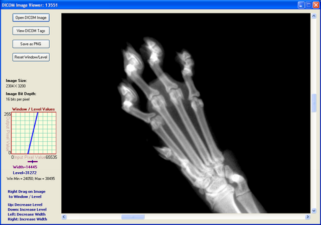
DICOM stands for Digital Imaging and COmmunication in Medicine. The DICOM standard addresses the basic connectivity between different imaging devices, and also the workflow in a medical imaging department. The DICOM standard was created by the National Electrical Manufacturers Association (NEMA), and it also addresses distribution and viewing of medical images. The standard comprises of 18 parts, and is freely available at the NEMA website: http://medical.nema.org. Within the innards of the standard is also contained a detailed specification of the file format for images. The latest version of the document is as of 2008. In this article, we present a viewer for DICOM images. We also demonstrate the way to modify the brightness and contrast of the displayed image through Window Level.


DicomViewerMainForm.PNG

DICOM Image File Format

We now present a brief description of the DICOM image file format. As with all other image file formats, a DICOM file consists of a header, followed by pixel data. The header comprises, among other things, the patient name and other patient particulars, and image details. Important among the image details are the image dimensions - width and height, and image bits per pixel. All of these details are hidden inside the DICOM file in the form of tags and their values.
Before we get into tags and values, a brief about DICOM itself and related terminology is in place. In what follows, we explain only those terms and concepts related to a DICOM file. In particular, we do not discuss the communication and network aspects of the DICOM standard.
Everything in DICOM is an object - medical device, patient, etc. An object, as in Object Oriented Programming, is characterized by attributes. DICOM objects are standardized according to IODs (Information Object Definitions). An IOD is a collection of attributes describing a data object. In other words, an IOD is a data abstraction of a class of similar real-world objects which defines the nature and attributes relevant to that class. DICOM has also standardized on the most commonly used attributes, and these are listed in the DICOM Data Dictionary (Part 6 of the Standard). An application which does not find a needed attribute name in this standardized list may add its own private entry, termed as a private tag; proprietary attributes are therefore possible in DICOM.
Examples of attributes are Study Date, Patient Name, Modality, Transfer Syntax UID, etc. As can be seen, these attributes require different data types for correct representation. This 'data type' is termed as Value Representation (VR) in DICOM. There are 27 such VRs defined, and these are AE, AS, AT, CS, DA, DS, DT, FL, FD, IS, LO, LT, OB, OF, OW, PN, SH, SL, SQ, SS, ST, TM, UI, UL, UN, US, and UT. For example, DT represents Date Time, a concatenated date-time character string in the format YYYYMMDDHHMMSS.FFFFFF&ZZXX. Detailed explanations of these VRs are given in Part 5 (Sec. 6.2) of the Standard (2008 version). An important characteristic of VR is its length, which should always be even.
Characterizing an attribute are its tag, VR, VM (Value Multiplicity), and value. A tag is a 4 byte value which uniquely identifies that attribute. A tag is divided into two parts, the Group Tag and the Element Tag, each of which is of length 2 bytes. For example, the tag 0010 0020 (in hexadecimal) represents Patient ID, with a VR of LO (Long String). In this example, 0010 (hex) is the Group Tag, and 0020 (hex) is the Element Tag. The DICOM Data Dictionary gives a list of all the standardized Group and Element Tags.
Also important is to know whether a tag is mandatory or not. Sec. 7.4 of Part 5 of the Standard (2008 version) gives the Data Element Type, where five categories are defined - Type 1, Type 1C, Type 2, Type 2C, and Type 3. If your application deals with, for instance, Digital X-Ray, then, refer to Part 3 of the Standard (2008 version), Table A.26-1 to identify the mandatory and non-mandatory tags for this. For example, from that table, again refer to C.7.1.1 to identify mandatory and non-mandatory tags corresponding to Patient. Repeat this for all entries in Table A.26-1. Similar is the case with other modalities.
One more important concept is Transfer Syntax. In simple terms, it tells whether a device can accept the data sent by another device. Each device comes with its own DICOM Conformance Statement, which lists all transfer syntaxes acceptable to the device. A Transfer Syntax tells how the transferred data and messages are encoded. Part 5 of the DICOM Standard gives the Transfer Syntax as a set of encoding rules that allow Application Entities to unambiguously negotiate the encoding techniques (e.g., Data Element structure, byte ordering, compression) they are able to support, thereby allowing these Application Entities to communicate. (One more term here -Application Entity is the name of a DICOM device or program used to uniquely identify it.) Transfer Syntaxes for non-compressed images are:
  • Implicit VR Little Endian, with UID 1.2.840.10008.1.2
  • Explicit VR Little Endian, with UID 1.2.840.10008.1.2.1
  • Explicit VR Big Endian, with UID 1.2.840.10008.1.2.2
Images compressed using JPEG Lossy or Lossless compression techniques have their own Transfer Syntax UIDs. A viewer should be able to identify the transfer syntax and decode the image data accordingly; or display appropriate error messages if it cannot handle it.
More points on a DICOM file:
  • It is a binary file, which means that an ASCII-character-based text editor like Notepad does not show it properly.
  • A DICOM file may be encoded in Little Endian or Big Endian byte orders.
  • Elements in a DICOM file are always in ascending order, of tags.
  • Private tags are always odd numbered.
With this background, it is now time to delve into the DICOM File Format. A DICOM file consists of these:
  • Preamble: comprising 128 bytes, followed by,
  • Prefix: comprising the characters 'D', 'I', 'C', 'M', followed by,
  • File Meta Header: This comprises, among others, the Media SOP Class UID, Media SOP Instance UID, and the Transfer Syntax UID. By default, these are encoded in explicit VR, Little Endian. The data is to be read and interpreted depending upon the VR type.
  • Data Set: comprising a number of DICOM Elements, characterized by tags and their values.
The main functionality of a DICOM Image Reader is to read the different tags, as per the Transfer Syntax, and then use these values appropriately. An image viewer needs to read the image attributes - image width, height, bits per pixel, and the actual pixel data. The viewer presented here can be used to view DICOM images with a non-compressed transfer syntax. Further, the DICOM file should be as per the latest version of the standard (2008 version).

DICOM Image Viewer Code

There are a number of freeware DICOM image viewers available. However, we could not find any viewer implemented in C#. ImageJ is a free Java-based viewer (with source code) capable of displaying images of many formats, including DICOM. Our intention here was to emulate the ImageJ code in C#, and create a no-frills simple viewer for DICOM files.
The functionality for this viewer is:
  • Open DICOM files with Explicit VR and Implicit VR Transfer Syntax
  • Read DICOM files where image bit depth is 8 or 16 bits. Also to read RGB DICOM files with bit depth of 8, and 3 bytes per pixel - these images are obtained from the Ultrasound modality.
  • Read a DICOM file with just one image inside it
  • Read a DICONDE file (a DICONDE file is a DICOM file with NDE - Non Destructive Evaluation - tags inside it)
  • Display the tags in a DICOM file
  • Enable a user to save a DICOM image as PNG
This viewer is not intended to:
  • Check whether all mandatory tags are present
  • Open files with VR other than Explicit and Implicit - in particular, not to open JPEG compressed Lossy and Lossless files
  • Read old DICOM files - requires the preamble and prefix for sure. Earlier DICOM files do not have the preamble and prefix, and just contain the string 1.2.840.10008 somewhere in the beginning. For our viewer, the preamble and prefix are necessary
  • Read a sequence of images
Though DICOM images frequently store their pixel data as JPEG-compressed, we have not included JPEG decompression in this application, since it would shift the focus elsewhere.
The code is written in C#, and built on Visual Studio 2008. The software itself is organized into a set of files as follows:
  1. DicomDictionary.cs, which contains the DICOM Dictionary, as contained in Part 6 of the Standard:
    class DicomDictionary
    {
       public Dictionary<string, string> dict = new Dictionary<string,string>()
       {
           {"20002", "UIMedia Storage SOP Class UID"}, 
           {"20003", "UIMedia Storage SOP Inst UID"},
           {"20010", "UITransfer Syntax UID"},
           {"20012", "UIImplementation Class UID"},
           {"20013", "SHImplementation Version Name"},
           ...
           {"FFFEE000", "DLItem"},
           {"FFFEE00D", "DLItem Delimitation Item"},
           {"FFFEE0DD", "DLSequence Delimitation Item"} 
       };
    }
  2. DicomDecoder.cs, whose main function is to parse the DICOM file and store the necessary attributes appropriately. One of the important methods here is intended to get the next tag:
    int GetNextTag()
    {
       int groupWord = GetShort();
       if (groupWord == 0x0800 && bigEndianTransferSyntax)
       {
          littleEndian = false;
          groupWord = 0x0008;
       }
    
       int elementWord = GetShort();
       int tag = groupWord << 16 | elementWord;
    
       elementLength = GetLength();
    
       // "Undefined" element length.
       // This is a sort of bracket that encloses a sequence of elements.
       if (elementLength == -1)
       {
          elementLength = 0;
          inSequence = true;
       }
       return tag;
    }
  3. ImagePanelControl.cs, reused from an earlier article written by us. This image panel contains inbuilt image scrolling should the image size become bigger than the display area.
  4. WindowLevelGraphControl.cs, which has the primary responsibility of displaying the graph control on the screen. An explanation of Window Level is given below.
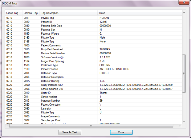
The main form has four buttons - for opening a DICOM file, for viewing the tags, for saving as a PNG file and for resetting to the original Window Level values. If the user wants to view the tags and their values, the following screen comes up, giving a list of the different tags present in the file.
DicomTags.PNG

Window Level and Window Width

An image when displayed is characterized by its brightness and contrast. When you increase the grayscale value of each of the pixels by one unit, then you're effectively increasing the brightness of the image by unity. Similarly with decreasing of the brightness. An image with overall low brightness appears dark; whereas one with overall high brightness appears bright. Contrast is a measure of the difference between the high and low values in an image. If two adjacent pixels have a large difference in grayscale values, the contrast between them is said to be high; conversely, if two adjacent pixels have a small difference in grayscale values, they are said to have a low contrast between themselves. Another way of representing brightness and contrast is through Window Level and Window Width. Stated in simple terms, Window Width is the difference between the brightest and dullest pixel value as displayed. And Window Level (also called Window Center) is the mid value between the brightest and dullest pixel value. Understanding these is simple if it is noted that there are four values involved:
  • Image Minimum, which is the minimum value among all grayscale values in any particular image
  • Image Maximum, which is the maximum value among all grayscale values in the image
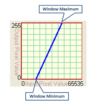
  • Window Minimum, which is the lower threshold value being displayed as zero intensity (dark) on the screen
  • Window Maximum, which is the higher threshold value being displayed as highest intensity (bright) on the screen
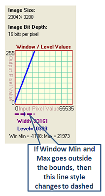
The first two values listed above depend on the image, whereas the next two values depend on the user's settings. All image pixels with grayscale intensity less than the Window Minimum are displayed as dark (zero intensity), whereas all image pixels with grayscale intensity greater than the Window Maximum are displayed as bright (maximum intensity, usually 255). Between the Window Minimum and Maximum values, a mapping function (linear or nonlinear) maps image grayscale values to displayed output valued. For purposes of this article, we restrict to a linear mapping as shown in the figure below (for a 16-bit image).
WindowLevelIntro.PNG
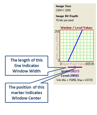
This can also be seen in another way. The brightness and contrast of an image can be adjusted to highlight features of interest. This is called "Windowing" of the image. When the image is windowed, the displayed shades of gray are adjusted. In essence, the Window Minimum and Window Maximum are manipulated so as to better see the image features. The Window Level is the middle value between Window Minimum and Window Maximum; in other words, it is the central value and is therefore also called Window Center. The larger this number, the darker appears the image; and vice versa. Window Width is the difference between Window Maximum and Window Minimum. Larger the difference, higher the contrast. For example, considering a 16-bit image, the user may want to focus on those pixels with intensities between 40000 and 50000; in this case, the Window Level becomes the midpoint value 45000, and Window Width becomes the difference value 10000. In this application, the rectangular window in the left of the screen shows the pixel mapping from input to output. The figure below gives an extract of the screen with just the Window / Level part shown. The Window Width is shown by the length of the purple line. Window Level is indicated by the position of the marker.
WindowLevel1.PNG
When the Window Minimum or Maximum fall outside the range of the original image, the line indicating Window Width changes to a dashed style as shown in the figure below:
WindowLevel2.PNG
To change Window Level and Width on the image, just right-drag (click and move the right mouse button) on the image. Right-drag in the vertical direction to modify Window Level. Right-drag in the horizontal direction to modify Window Width. You may save the image as PNG with the current Window Level settings.

Known Issue

When you open an image and press the Alt button, the image disappears. However, it comes back after forced repainting, say by minimizing and restoring the viewer window.

Closure

In this article, a simple application to display a DICOM file was described. The DICOM jargon was explained briefly followed by a brief explanation of the DICOM file format. This application was heavily inspired by ImageJ. The viewer shown here can be used to view files with Transfer Syntax of Explicit and Implicit VR, and not for those containing compressed image data. You may also modify the Window Width and Level of the image by right-dragging on it.

Dicom Image


Converting a DICOM image to a common graphic format and vice versa with DCMTK and CxImage


Introduction

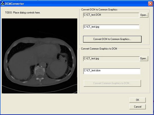
This article presents a minimum runnable toy application as a starting point to show how to convert a DICOM image to common graphic formats (i.e. BMP, JPG, TIF, etc.) and vice versa. Our sample application is based on two open source libraries, they are DCMTK and CxImage.

Background

The DICOM standard (Digital Imaging and Communications in Medicine) is a standard created by the National Electrical Manufacturers Association (NEMA) to ease the distribution and exchange of medical images, such as CT scans, MRIs and ultrasound. In this article, we will focus on file format conversions. The file format is described in Part 10 of the DICOM standard, which you can download from here[^]. There is also a brief introduction to the file format available here.
DCMTK is a widely used open source implementation of the DICOM standard; it is a collection of C/C++ libraries and applications with complete source code. To compile the sample in this article you need to download DCMTKfirst. If you have trouble building the downloaded DCMTK package, please refer to DCMTK for Dummies.
Another library used in this article is CxImage, it is a C++ class that can load, save, display and transform images in a very simple and fast way. It supports almost all the common graphic types, such as BMP, JPG, TIF, PNG, etc. In this article, we will expand this library to support displaying and transforming DICOM images by using the DICOM format encoding/decoding features provided by DCMTK. Download CxImage and follow its usage guidance to make sure it can be compiled successfully on your machine.

Using the code

We simply derive our CxImageDCM class from the base class CxImage. Doing so, enables CxImageDCM class to load and decode common graphics using the methods inherited from the base class. There are three extra methods in the derived class, LoadDCM(…)SaveAsDCM(…)SaveAsJPG(…), they are used to decode, encode and convert a DICOM image, respectively.
//
class CxImageDCM : public CxImage  
{
public:
    CxImageDCM();
    virtual ~CxImageDCM();
    
    bool LoadDCM(const TCHAR* filename);
    bool SaveAsDCM(const TCHAR* filename);
    bool SaveAsJPG(const TCHAR* fileName);

};//

Load DCM

In the sample application, a DICOM image is loaded and decoded with the classes provided by DCMTK, then it is converted to a temporary bitmap file for later manipulations:
//
bool CxImageDCM::LoadDCM(const TCHAR* filename)
{  
    DcmFileFormat *dfile = new DcmFileFormat();
    OFCondition cond = dfile->loadFile(filename, EXS_Unknown,
                      EGL_withoutGL,DCM_MaxReadLength,OFFalse);
    
    if (cond.bad()) {
        AfxMessageBox(cond.text());
    }
    
    E_TransferSyntax xfer = 
            dfile->getDataset()->getOriginalXfer();
    DicomImage *di = new DicomImage(dfile, xfer, 
                         CIF_AcrNemaCompatibility, 0, 1);
    
    if (di->getStatus() != EIS_Normal)
        AfxMessageBox(DicomImage::getString(di->getStatus()));
    
    di->writeBMP("c:\\from_dicom.bmp",24);
    
    return CxImage::Load("c:\\from_dicom.bmp",CXIMAGE_FORMAT_BMP);
    
}//

Converting from DCM

After loading a DCM file, you can save it as a common graphic file using the encoding features provided byCxImage, or you may also use DCMTK’s encoding plugins to do the conversion (however, CxImage supports more formats):
//
bool CxImageDCM::SaveAsJPG(const TCHAR* fileName)
{//you may also use DCMTK's JPG encoding plug-in
    return CxImage::Save(fileName,CXIMAGE_FORMAT_JPG);

}//

Converting to DCM

To convert a common graphic file to a DCM file, you need to load the common graphic first, then set the necessary tag and copy the pixel data to the destination DCM file:
//
bool CxImageDCM::SaveAsDCM(const TCHAR* filename)
{
    CxImageDCM::IncreaseBpp(24);
    char uid[100]; 
    DcmFileFormat fileformat; 
    DcmDataset *dataset = fileformat.getDataset(); 
    dataset->putAndInsertString(DCM_SOPClassUID, 
               UID_SecondaryCaptureImageStorage); 
    /* ... */
    //dataset->putAndInsertUint32(DCM_MetaElementGroupLength,128);
    dataset->putAndInsertUint16(DCM_FileMetaInformationVersion,
                                                          0x0001);
    /* ... */    
    dataset->putAndInsertString(DCM_UID,
        UID_MultiframeTrueColorSecondaryCaptureImageStorage);
    dataset->putAndInsertString(DCM_PhotometricInterpretation,
                                                        "RGB"); 
    //add more tags here
    /* ... */ 
    BYTE* pData=new BYTE[GetHeight()*info.dwEffWidth];
    BYTE* pSrc=GetBits(head.biHeight-1);
    BYTE* pDst=pData;
    for(long y=0; y < head.biHeight; y++){
        memcpy(pDst,pSrc,info.dwEffWidth);
        pSrc-=info.dwEffWidth;
        pDst+=info.dwEffWidth;
    }
    dataset->putAndInsertUint8Array(DCM_PixelData, 
                 pData, GetHeight()*info.dwEffWidth); 
    delete[] pData;
    
    OFCondition status = fileformat.saveFile(filename, 
                           EXS_LittleEndianImplicit,
                           EET_UndefinedLength,EGL_withoutGL); 
    if (status.bad()) 
        AfxMessageBox("Error: cannot write DICOM file ");
    
    return true;     
}//

Points of interest

In this article, the encoding feature provided by CxImage is used to convert a DICOM image to a JPG file (or other formats that CxImage supports). Actually, DCMTK already has a full-fledged utility called dcmj2pnm to convert a DICOM image to a BMP, PNG, TIF or JPG image. For other formats, that dcmj2pnm doesn’t support, such as GIF, TGA, PCX, WBMP, etc., you may use CxImage’s encoding features to write your own converting functions. One thing that I need to clarify here is that our sample application is only a toy utility to give you a starting point. To write a decent DICOM image converter, you need to consider many more DICOM related options. For more information, you can refer to the implementation of dcmj2pnm. (It is included in the DCMTK source code package.)
From my experience, CxImage is easy to use; it "can load, save, display and transform images in a simple and fast way". However, I find it annoying when you have to derive a new image encoder/decoder from the base class, CxImage. The base class must know all the derived classes to give a polymorphic behavior. Fortunately, in our sample, the derived class CxImageDCM needs only the encoding/decoding functions it inherits from the base class, so I didn’t bother to touch the source code of CxImage.

Using Trigonometry and Pythagoras to WaterMark an Image


Introduction

The class presented here will place a watermark on an image. It takes a Bitmap object and returns anotherBitmap with a string drawn diagonally (top-left to bottom-right) across it. An instance of the class is constructed with the actual text to place, font properties, maximum wanted font size (more on this in a bit),Color and transparency (byte).
This may sound fairly trivial but calculating the angle of the diagonal line through a Rectangle of unknown Size at design time (big d'oh! if there's a library method that already does this!) and autosizing the font to fill as much of the bitmap as possible, without being clipped involves Trigonometry and Pythagoras. This is what I aim to show here.

Background

I answered this question in the C# forum with a quick and dirty answer. The original poster seemed happy with my answer but I was spurred on to make it better.
I have done a bit of development on image filters before and have modeled my class structure based on this article, by Andrew Kirillov (recommended reading if you are interested in learning about GDI+). The class in my article also uses this structure. I have, however, removed the IFilter interface for the purpose of this article as I am only covering 1 class and it would detract from the focus (if you don't know what I mean by that last sentence then forget I said anything, it doesn't matter :) ).
I am a tester by trade but I have taught myself C# over the course of the last 3 years. The way I have solved the problem here may not be the quickest, easiest or optimum approach. I just used my current knowledge of C# and tried to remember my school Trigonometry and Pythagoras as best I could. I'm sure there are ways for further improvement. A couple of ideas that come to mind is an enum to select which way to draw the watermark (eg diagonally-down, diagonally-up, horizontal etc) or being able to handle multiple lines of text. Any comments or suggestions for improvement are most welcome.

Using the code

I decided to solve this problem by breaking it down into bite size pieces, solving each part separately and building up my class progressively.

1. Draw a string on an image

The starting point. Below is the basic structure of the class which draws the supplied string to the Bitmapobject. Simply placed at 0,0 with no fancy transparency, angles or resizing.
using System;
using System.Drawing;
using System.Drawing.Drawing2D;

namespace DM.Imaging
{
   public class WaterMark
   {
      private string waterMarkText;
      private string fontName;
      private FontStyle fontStyle;
      private Color color;
      private int fontSize;

      public WaterMark(string waterMarkText, 
                       string fontName, int fontSize,
                       FontStyle fontStyle, Color color)
      {
         this.waterMarkText = waterMarkText;
         this.fontName = fontName;
         this.fontStyle = fontStyle;
         this.color = color;
         this.fontSize = fontSize;
      }

      public Bitmap Apply(Bitmap bitmap)
      {
         Bitmap newBitmap = new Bitmap(bitmap);
         Graphics g = Graphics.FromImage(newBitmap);

         Font font = new Font(fontName, fontSize, 
                              fontStyle);

         g.DrawString(waterMarkText, font,  
                      new SolidBrush(color), new Point(
                      0, 0));

         return newBitmap;
      }
   }
}
This is a simplification of what it produces:

2. Place string diagonally

Ok, so now I need to calculate the angle. Here we use a bit of Trigonometry. Remember SOHCAHTOA? If we draw an imaginary diagonal line through our bitmap then we end up with a right-angled triangle:
By the basic rules of Trigonometry we can calculate the tangent of the angle by dividing the length of the opposite side by the length of the adjacent side. In this case, dividing the bitmap's height by its width:
double tangent = (double)newBitmap.Height / 
                 (double)newBitmap.Width;
We can then calculate the angle from it's tangent by using the Math.Atan method, like so:
double angle = Math.Atan(tangent) * (180 / Math.PI);
All we need to do now is apply this angle to our Graphics object before we draw the string:
g.RotateTransform((float)angle);
This is just about where we've got:

3. Draw the string in the middle

Now I need to move the string so that it is drawn dead-centre of the bitmap. Therefore, we need to draw the string half way along our diagonal line. This is where Pythagoras comes in. If we go back to our imaginary triangle, we will see that we can calculate the length of the diagonal line, or the hypotenuse, by the formula a^2 = b^2 + c^2 or a = sqrt(b^2 + c^2).
This will translate to:
double halfHypotenuse = Math.Sqrt((newBitmap.Height * 
       newBitmap.Height) + (newBitmap.Width * 
       newBitmap.Width)) / 2;            
All we need to do then is tweak the DrawString method to adjust the position of the string:
g.DrawString(waterMarkText, font, new SolidBrush(color), 
             new Point((int)halfHypotenuse, 0));
We're getting closer, but still not right:

4. Centre the string

The string is being drawn, by default, from the top-left of the Point we specify in the DrawString method. We can change this to the centre of the string by simple creating a StringFormat object, setting its alignment properties:
StringFormat stringFormat = new StringFormat();
stringFormat.Alignment = StringAlignment.Center;
stringFormat.LineAlignment = StringAlignment.Center;
...and adding this to the DrawString method, as this method has another overload which takes this as a parameter:
g.DrawString(waterMarkText, font, new SolidBrush(color), 
           new Point((int)halfHypotenuse, 0),stringFormat);
This is starting to look more like it:

5. Autoresize string

Have I bored you to death or are you still with me? If you're not asleep now, you will be after this section! Now, I want the user to be able to select a font size. But, if the size they select would clip some of the text (ie some of the string is drawn off the edge of the bitmap) then I want to automatically shrink the font so that it does fit.
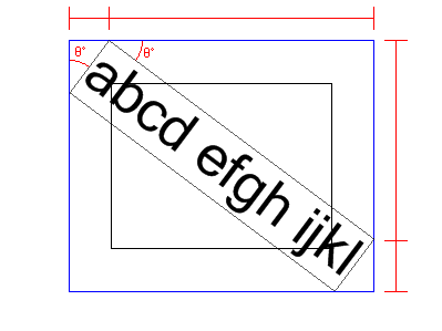
If we imagine what a string that is too big will look like on the bitmap, and draw a rectangle around it. Then we see that we need to compare this imaginary (blue) rectangle with the bitmap dimensions. If the blue rectangle is bigger than the bitmap, then we know that we need to shrink the font, and check the again:
The hard part is calculating the Size of this imaginary blue rectangle. Firstly, we can measure how big the string will be by calling the Graphics.MeasureString method:
SizeF sizef = g.MeasureString(waterMarkText, font, 
                              int.MaxValue);
Now we have this, if we look at the picture in my head again, we see that we can split the blue rectangle up into triangles and split both the width and height into two Trig calculations (4 total) that we sum to give us the overall size. We already have the angle from our calculations before and we now know the hypotenuse for both the little and big triangles (sizef.Height and sizef.Width respectively):
If we take the width of the big blue triangle first. To start, if we look at the smaller triangle we need to calculate the length of the side which is opposite to the angle we know and we have the hypotenuse. Using trig (sine) we can calculate this as follows:
double sin = Math.Sin(angle * (Math.PI / 180));
double opp1 = sin * sizef.Height;
If we repeat this methodology for the large triangle... We need to calculate the length of the side which is adjacent to the angle we know and we have the hypotenuse. This will be a cosine calculation:
double cos = Math.Cos(angle * (Math.PI / 180));
double adj1 = cos * sizef.Width;
We then just sum opp1 and adj1 to get the width. We repeat this for the height. At the end we check if the blue rectangle is smaller than the bitmap. If it isn't then we shrink the font down a bit and repeat the check. Once the string fits then we are good to go.
It may have been wiser to pull these statements out into their own method as using a break; in a for loop seems a bit dirty to me. But it works! So I'm not complaining. Here's the complete for loop:
Font font = new Font(fontName, maxFontSize, fontStyle);
for (int i = maxFontSize; i > 0; i--)
{
   font = new Font(fontName, i, fontStyle);
   SizeF sizef = g.MeasureString(waterMarkText, font, 
                                 int.MaxValue);

   double sin = Math.Sin(angle * (Math.PI / 180));
   double cos = Math.Cos(angle * (Math.PI / 180));

   double opp1 = sin * sizef.Height;
   double adj1 = cos * sizef.Width;

   double opp2 = sin * sizef.Width;
   double adj2 = cos * sizef.Height;

   if (opp1 + adj1 < newBitmap.Width &&
       opp2 + adj2 < newBitmap.Height)
   {
      break;
   }
}
Here a recap on where we're up to:

6. Make transparent and Antialias

We're on the home straight now. My head's beginning to hurt! All there is left to do is add the finishing touches. Drawing text at a rotated angle can look a bit, let's say, wrong. so it can't hurt to add some Antialias:
g.SmoothingMode = SmoothingMode.AntiAlias;
Transparency is added by changing the alpha level of the color, with 0 = invisible up to 255 = opaque.
public WaterMark(string waterMarkText, string fontName, 
                 int maxFontSize, FontStyle fontStyle, 
                 Color color, byte alpha)
{
   // ...
   this.color = Color.FromArgb(alpha, color);
}
And the finished result:
Well, that's it. Done. Here's the entire class:
using System;
using System.Drawing;
using System.Drawing.Drawing2D;

namespace DM.Imaging
{
   public class WaterMark
   {
      private string waterMarkText;
      private string fontName;
      private FontStyle fontStyle;
      private Color color;
      private int maxFontSize;

      public WaterMark(string waterMarkText, 
                       string fontName, int maxFontSize,
                       FontStyle fontStyle, Color color, 
                       byte alpha)
      {
         this.waterMarkText = waterMarkText;
         this.fontName = fontName;
         this.fontStyle = fontStyle;
         this.color = Color.FromArgb(alpha, color);
         this.maxFontSize = maxFontSize;
      }

      public Bitmap Apply(Bitmap bitmap)
      {
         Bitmap newBitmap = new Bitmap(bitmap);
         Graphics g = Graphics.FromImage(newBitmap);

         // Trigonometry: Tangent = Opposite / Adjacent
         // Remember SOHCAHTOA?
         double tangent = (double)newBitmap.Height / 
                          (double)newBitmap.Width;

         // convert arctangent to degrees
         double angle = Math.Atan(tangent) * (180/Math.PI);

         // Pythagoras here :-/
         // a^2 = b^2 + c^2 ; a = sqrt(b^2 + c^2)
         double halfHypotenuse =Math.Sqrt((newBitmap.Height 
                                * newBitmap.Height) +
                                (newBitmap.Width * 
                                newBitmap.Width)) / 2;

         // Horizontally and vertically aligned the string
         // This makes the placement Point the physical 
         // center of the string instead of top-left.
         StringFormat stringFormat = new StringFormat();
         stringFormat.Alignment = StringAlignment.Center;
         stringFormat.LineAlignment=StringAlignment.Center;

         // Calculate the size of the string (Graphics
         // .MeasureString)
         // and see if it fits in the bitmap completely. 
         // If it doesn’t, strink the font and check 
         // again... and again until it does fit.
         Font font = new Font(fontName,maxFontSize,
                              fontStyle);
         for (int i = maxFontSize; i > 0; i--)
         {
            font = new Font(fontName, i, fontStyle);
            SizeF sizef = g.MeasureString(waterMarkText, 
                           font, int.MaxValue);

            double sin = Math.Sin(angle * (Math.PI / 180));
            double cos = Math.Cos(angle * (Math.PI / 180));

            double opp1 = sin * sizef.Width;
            double adj1 = cos * sizef.Height;

            double opp2 = sin * sizef.Height;
            double adj2 = cos * sizef.Width;

            if (opp1 + adj1 < newBitmap.Height &&
                opp2 + adj2 < newBitmap.Width)
            {
               break;
            }
         }
         
         g.SmoothingMode = SmoothingMode.AntiAlias;
         g.RotateTransform((float)angle);            
         g.DrawString(waterMarkText, font, 
                      new SolidBrush(color),
                      new Point((int)halfHypotenuse, 0), 
                      stringFormat);

         return newBitmap;
      }
   }
}

Using the sample project

It should be fairly straight forward to see what's happening. Try resizing the form to see the watermark be updated on the fly.

Popular Posts